Ryzen, Vega, and 1080 Ti news has flanked another major launch in the hardware world, though this one is outside of the PC space: Nintendo’s Switch, formerly known as the “NX.”
We purchased a Nintendo Switch ($300) specifically for teardown, hoping to document the process for any future users wishing to exercise their right to repair. Thermal compound replacement, as we learned from this teardown, is actually not too difficult. We work with small form factor boxes all the time, normally laptops, and replace compound every few years on our personal machines. There have certainly been consoles in the past that benefited from eventual thermal compound replacements, so perhaps this teardown will help in the event someone’s Switch encounters a similar scenario.
Nintendo Switch Disassembly: Tools Required
The Nintendo Switch requires only a few tools. We used our iFixit Pro Tech Toolkit for this teardown (they also sponsored the coverage, as we needed some specific pieces for this). The primary tools are:
- Phillips Head screwdrivers (small + medium A1 sizes needed)
- Y-Shape Tri-Wing screwdriver
- Rubbing alcohol if removing thermal compound
- Thermal compound if replacing
The iFixit Pro Tech Toolkit ($70) contains the uncommon Y-drive screws, alongside spudgers, pliers/priers, and other useful tools for PC building or disassembly. We would also suggest a magnetic mat so that you can draw an outline of the Switch and then track the specific locations of the screws. This will help reduce the chance of reassembling and leaving out a screw.
Note: We don't recommend doing this. There's a good chance you'll damage something, and "damage" normally means "broken beyond repair" in a lot of instances. This is not a tutorial, just a walkthrough of what we did.
Nintendo Switch: Remove Backplate
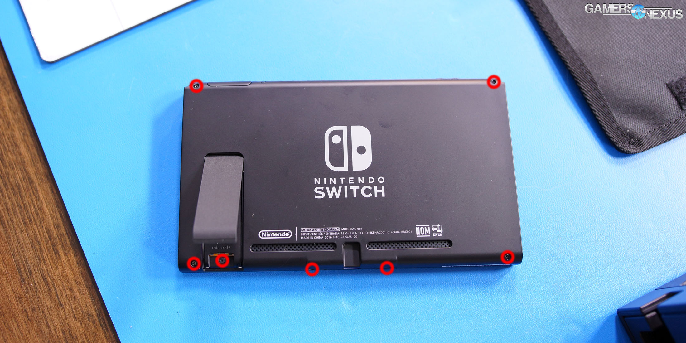
Removing the backplate is easy. We will need to remove each of the screws in the highlighted positions:
Note: The four outer screws are longer and are Y-drive/tri-wing screws. You cannot use a Phillips driver on these. The other, smaller screws are Phillips heads.
This will loosen the backplate. Note that there is one hidden screw under the kickstand. This screw threads into the microSD card receptacle on the inside of the Switch body and must be removed to dismount the backplate.
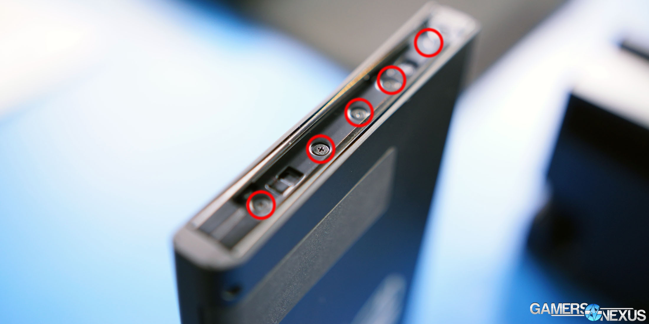
We'll next have to remove five Phillips screws on either side of the Switch body. The screws are located within the charging rails for the Joycons. Upon removing these screws, the rails will become limp (but won’t fall off entirely) and will remain attached by a charging cable. Be sure that this cable is not disconnected or severed from the rails.
The backplate can now be removed. Gently place the spudger between the backplate and the Switch body where there is the largest spacing. Apply very light shimming force. There are some clips retaining the backplate to the body, and these will pop (not snap, but pop) out of their sockets as we shim along the perimeter. If any resistance is met, we stop and look for a screw. This should not require significant force.
Under the Backplate
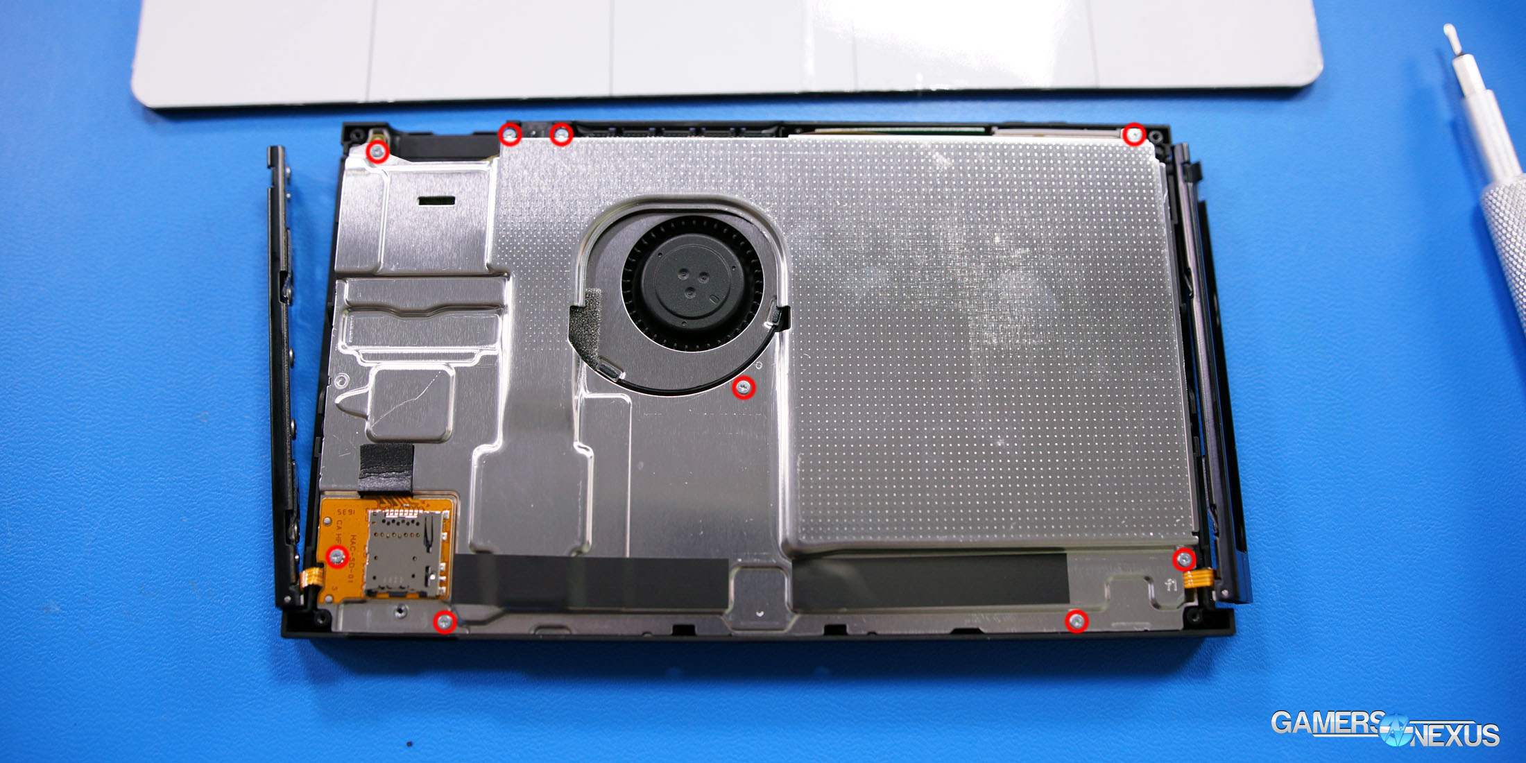
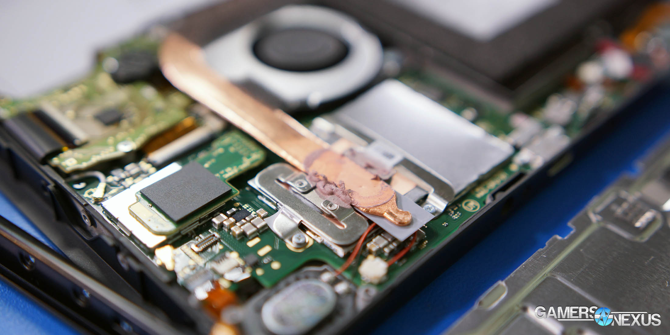
With the backplate removed, we can now remove the conductor plate. There's a 25mm radial fan located off-center within the Switch; this is ultimately connected to the SOC and cooling solution (which uses an 8mm heatpipe).
To remove this plate, find these screws:
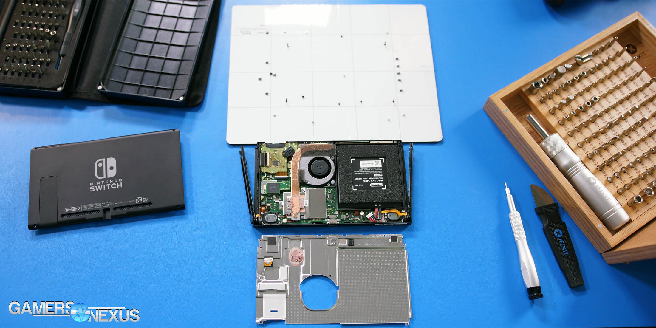
We like to line the screws in inner and outer layers on a magnetic mat to better remember the rebuild process, sort of like this:
Getting this far into the Switch, we can now see some of the components that are used in the build. The battery is labeled as “HAC-003,” and is a Lithium-Ion 3.7V battery at 4310mAh. An embedded Flash module (local storage) contains both the controller and NAND, and is Samsung module KLMBG2JENB-B041.
As for the audio, it’s handled by a Realtek ALC5639 chip, similar to what’s found on the Tegra Jetson boards from nVidia. USB is by Pericom with the P13USB IC.
Disconnect the battery cable before proceeding and allow a moment for any standby voltage to drain.
Finally, to reveal the SOC, we'll have to remove a few screws flanking the heatpipe and fan, then remove the (combined) heatsink+fan unit. Under this, we’ll reveal the cover for the SOC. Remove the cover by gently prying under the corners, then use fingers to remove the cover the rest of the way. Be careful not to bend the cover.
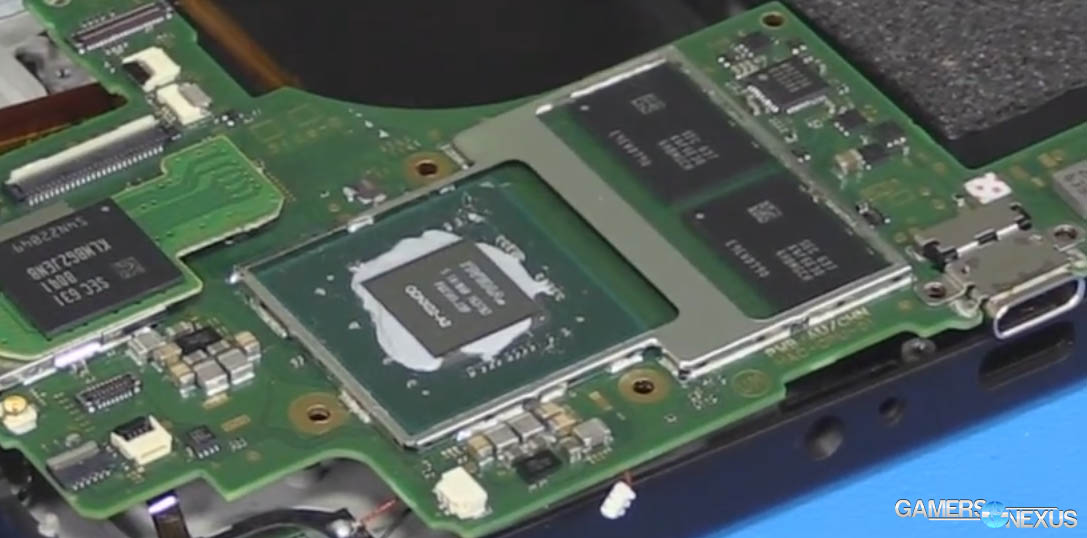
We can now see the SOC (ODNX02-A2), which seems to be a modified Tegra X1 (Maxwell, despite our initial speculation that it’d be Pascal). This is accompanied by two memory modules, which we think to be 2GB units (4GB total).
We have a few more plans for the Switch, assuming we can get through the rest of the usual CPU and GPU benchmarking for the week. Definitely a fun project!
Editorial: Steve Burke
Video: Andrew Coleman
